• ABOUT

PROJECT OBJECTIVES

The main objective of FLHYSAFE is to demonstrate that a cost efficient modular fuel cell system can replace the most critical safety systems and be used as an Emergency Power Unit (EPU) aboard a commercial airplane providing enhanced safety functionalities. Additionally, the project will virtually demonstrate that the system is able to be integrated into current aircraft designs respecting both installation volumes and maintenance constraints.

To fulfil its main objectives, two technical objectives will allow to deliver a safe and reliable FC system based EPU at TRL 6 and help pave the way for the third specific objective, which will allow the preparation of the project follow up and moves towards higher TRL. The long-term specific objective is thus to pave the way for the industrialisation and commercialisation through the involvement of other stakeholders (airframers, airliners, authorities), through exploitation plans and management of IPs and through the promotion of the project results thanks to an efficient communication and dissemination plan.

FLHYSAFE has thus three specific objectives:

1. Design a modular Fuel Cell based Emergency Power Unit with a power range from 15kw to 60kw

2. Develop and validate the FC system based EPU at TRL 5-6

3. Prepare the roadmap for exploitation

EXPECTED RESULT

The EPU to be developed in FLHYSAFE will offer improved functionalities and performance in comparison with current RATs. Thanks to the hybridisation of the fuel cell stack with a secondary power source, a battery, the system will be able to start-up within 5 seconds as required for an EPU.
The fuel cell based FLHYSAFE EPU will offer an operating time of up to 3 hours with full power availability all along the mission, independently from the aircraft speed, until the aircraft is stopped and safe on the ground.

This functionality will be an important breakthrough compared to the actual RAT and will increase safety during the most critical phase of an emergency landing.

A fuel cell based EPU, contrary to a RAT, can be located in many different locations of the aircraft as it does not require to unfold or to directly interact with the exterior environment. As a consequence, the developed system will be generic and possible to integrate into different types of aircraft.

APPROACH

The FLHYSAFE concept, is to develop a modular fuel cell system architecture, scalable by steps of 15 kW, in order to address a wide market power requirement. Safran Power Units (SPU), major aeronautical equipment suppliers, will develop an innovative fuel cell-based emergency technology using PEM fuel cell stacks developed by Safran Aerosystems (formerly Zodiac Aerotechnics) and CEA. This system will be validated by DLR and INTA through ground full scale tests. This fuel cell system will be designed with a modular power range approach from 15 kW to 60 kW. The modularity of the system will be obtained by duplicating the main elementary components such as (but not limited to) the Fuel Cell Stack and power electronics, the air compressor and the hydrogen storage.

This modularity will allow to address various power demands according to the different single aisle aircraft needs with a common system architecture and common equipment sizing and development. This modular approach will also bring redundancy for the critical functions which will improve the reliability of the whole system. For the demonstrator, a fuel cell system prototype of 15 kW will be developed. Thanks to the experience of the participants in previous projects, the necessary tests will be carried out in order to demonstrate compatibility to representative environment and safety levels.

WORKPLAN

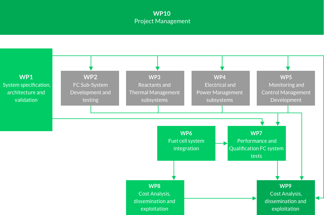
The project is structured through a sequential research and innovation
process to develop the final solution. The work plan for FLHYSAFE is
broken down into 8 technical work packages, 1 business analysis,
dissemination and exploitation work package and
1 management work package.

Lasting 51 months it will be structured into the following WP (Work
Packages) and with the following breakdown.

Organigramm

WP1 ‘System specification, architecture and validation’ is dedicated to the development of the architecture design of the emergency power unit system with the agreed requirements. Within this WP the plans of environmental tests to get airworthiness qualification will be prepared.

WP2 ‘FC Sub-System Development and testing’ will take care of the design and development of the FC Sub-System. Several preliminary validations in terms of performances at sub system level and lifetime testing will take place in this WP to reach optimised results.

WP3 ‘Reactants and Thermal Management subsystems’ will specify the different subsystems from the system specifications given in WP1. The definition and the sizing of the components of the different subsystems will be defined in WP3 in order to proceed to test and validate them prior to integrate them in the whole emergency power unit system.

WP4 ‘Electrical and Reactants and Thermal Management subsystems’ Management Subsystem’ is dedicated to the specification of the Electrical and Power Management Subsystem (EPMS) given in WP1. The definition and size of the development and validation of a power converter integrated to the fuel cell stack will be also achieved in WP4 along with the validation of its performance.

WP5 ‘Monitoring and Control Management Development’ will perform the from the system Specification in WP1. This WP will define the safety and the control logic for all the normal and abnormal operating sequences. Software and hardware components for the Fuel Cell and the Fuel Cell Safety controllers will be developed in WP5.

WP6 ‘Fuel cell system integration’ will develop an optimal design of an assembled emergency power unit system while ensuring its proper behaviour in terms of over-heating and safety.

WP7 ‘Performance and Qualification FC system tests’ will demonstrate the safety of the Emergency Power Unit System while validating its overall performances. It will also demonstrate that the FC system can operate with the environmental requirements for an airborne equipment, while analysing if the system developed complies with DO 160 environmental conditions and procedures according to the defined type of aircraft.

WP8 ‘Virtual reality for aircraft implantation and maintenance procedures’ will be dedicated to enable a virtual projection of the complete fuel cell system to anticipate to ensure that assembly and maintenance will be feasible. The developed virtual reality tool will perform a projection of the complete system into a specific area of a given aircraft to analyse interactions between both.

WP9 ‘Cost Analysis, dissemination and exploitation’ is dedicated to the activities foreseen to prepare the project follow up and moves towards higher TRL (especially flight tests), to analyse cost aspects (acquisition, operations and maintenance), to prepare the industrialisation and commercialisation through the involvement of other stakeholders (airframers, airliners, authorities), exploitation plans and management of IPs and to promote the project results through communication.

WP10 ‘Project Management’ transverse across all activities conducted during the project. It comprises the project administration as well as the overall technical consistency, convergence and assessment towards FLHYSAFE objectives through efficient monitoring and reporting activities.